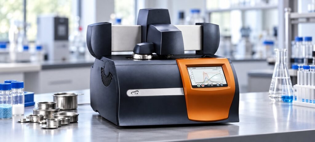
DSC Heating Rate Effect: Compare Peaks
 testDSC.Admin
The DSC heating rate effect is the change in a reported transition temperature as the programmed ramp changes. Because β equals dT/dt, increasing β can move a transformation peak higher through thermal lag and reaction kinetics. A paired-ramp comparison using the same sample mass, pan condition, purge, and temperature window shows whether the shift is reproducible enough to guide your specification.
That comparison is the practical gap between published DSC guidance and a defensible service result. You need to separate a real rate-dependent response from changes caused by pan sealing, sample mass, thermal history, or poor repeatability.
How does the DSC heating rate effect move a peak?
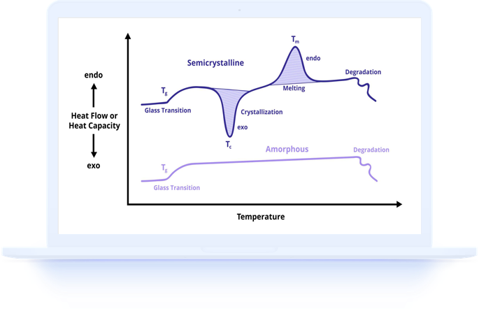
The DSC heating rate effect usually moves a transformation peak to higher temperature as the ramp increases. The Cambridge 2026 page defines β as dT/dt and attributes the movement to shorter reaction time, temperature-dependent kinetics, and instrument thermal lag.
The same page notes that increasing β from 2 °C/min to 50 °C/min pushes the peak apex rightward through both kinetic and lag effects. Report onset and peak separately. A DSC peak shift is not automatically a new material transition.
For broader terminology and reporting context, use our differential scanning calorimetry dsc analysis guide. The paired-ramp question here is narrower: how much movement occurs when only the heating rate changes?
See also: DSC Test False Peaks: Artifact or Real Transition?
What sample setup makes a DSC ramp comparison fair?
A fair comparison holds sample mass, pan construction, sealing, reference pan, purge gas, and temperature limits constant. The University of Florida’s Experimental Conditions: DSC guidance gives typical sample amounts of 5–10 mg, with more material generally needed below 10 °C/min and less near 20 °C/min.
| Ramp choice | Sample guidance | Use when |
|---|---|---|
| Below 10 °C/min | A larger amount may support weak transitions | You need more signal at a slower DSC ramp rate |
| 10 °C/min | A 5–10 mg working range is typical | You need a practical reporting baseline |
| Near 20 °C/min | A smaller amount is generally preferred | You need a faster comparison condition |
The same University of Florida guidance recommends starting between 2 mg and 6 mg, increasing toward 10 mg only when the transition is weak, and normally avoiding samples above 10 mg. Keep the reference pan matched to the sample pan type. For the closest comparison, keep reference and sample pans within 0.5 mg.
A flat pan bottom, good sample contact, and a sound seal matter because leakage, deformation, or a thermal gradient can imitate a rate effect. If you need instrument-component context before specifying the run, see Understanding DSC Instruments: Types, Components, and How They Work.
See also: DSC Testing for Aerospace Materials: Ensuring Safety and Performance
How should you design a paired-ramp test?
Use two heating rates on comparable portions of the same customer-supplied material, with one controlled variable: the ramp. A practical starting pair is 10 °C/min and 20 °C/min when the sample tolerates both conditions.
- Prepare representative portions at the same target mass. Failure mode — unequal mass or different particle size changes heat transfer and weakens the comparison.
- Use the same pan type, lid condition, sealing method, and matched empty reference. Failure mode — a leaking or deformed pan can create a false onset or peak movement.
- Keep purge gas and flow constant, then run 10 °C/min and 20 °C/min across the same temperature window. Failure mode — a changed atmosphere or range introduces a second experimental variable.
- Report onset, peak, and enthalpy for both ramps, then calculate the 20 °C/min minus 10 °C/min change. Failure mode — reporting only the higher peak hides whether the onset or enthalpy also moved.
AMI’s Nylon Degradation Analysis by DSC gives a useful thermal-history example: first heat at 20 °C/min, cool at 10 °C/min, second heat at 20 °C/min, with nitrogen at 50 mL/min. Treat that sequence as conditioning plus measurement, not as a clean paired-ramp comparison, because the rates occur in different cycle legs.
If your report follows ISO 11357-1:2016, Clause 10, include the specimen mass, crucible condition, atmosphere, gas flow, heating rate, temperature results, and enthalpy basis. For sample handling workflow, our DSC Experiment Setup: A Beginner’s Guide to Running Your First Test is the next practical reference.
What does a TestDSC paired-ramp result show?
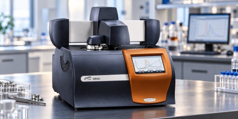
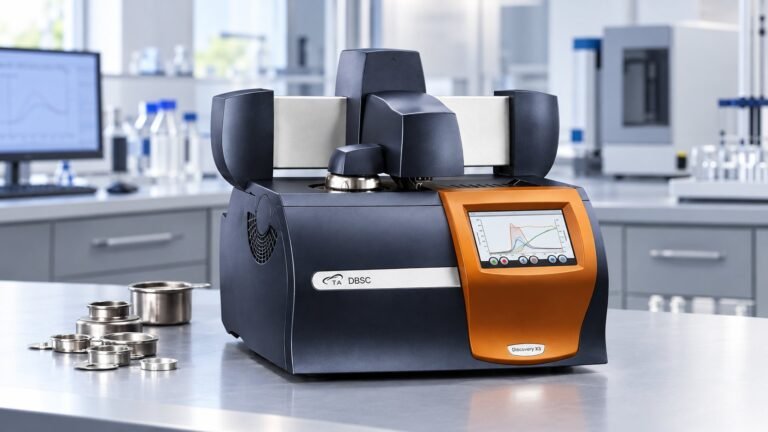
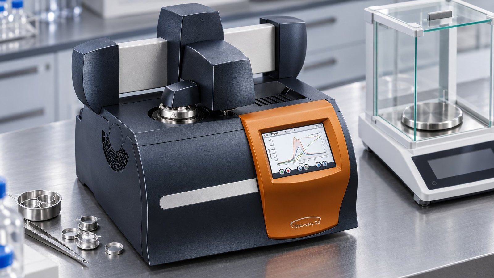
An anonymized TestDSC service record shows the reporting detail needed to evaluate a DSC heating rate comparison. The customer supplied one polymer sample. Both runs used the same Discovery X3 reporting baseline mass of 7.84 mg.
| Measured item | 10 °C/min | 20 °C/min | Measured change, 20 minus 10 |
|---|---|---|---|
| Sample mass | 7.84 mg | 7.84 mg | 0.00 mg |
| Pan condition | Sealed aluminum pan; matched empty reference | Sealed aluminum pan; matched empty reference | No change |
| Purge | Nitrogen, 50 mL/min | Nitrogen, 50 mL/min | No change |
| Onset temperature | 154.2 °C | 156.0 °C | +1.8 °C |
| Peak temperature | 161.5 °C | 164.2 °C | +2.7 °C |
| Enthalpy | 43.6 J/g | 42.9 J/g | −0.7 J/g |
The 10 °C/min run is a reporting baseline, not proof of a rate effect by itself. In the paired record, the higher ramp produced a +2.7 °C peak movement and a +1.8 °C onset movement, while enthalpy changed by −0.7 J/g. The direction agrees with the Cambridge explanation, but one run at each rate does not establish statistical significance.
How do you decide whether a DSC peak shift is meaningful?
A peak shift is meaningful when it exceeds the method’s repeatability and remains after the sample, pan, purge, and thermal history are controlled. Use replicate runs when the decision affects a release limit, formulation change, or process specification.
- Compare peak temperature and onset temperature separately.
- Report the signed difference in °C, not only a percentage.
- Check whether enthalpy changes materially in J/g.
- Repeat each ramp when the observed difference is close to your method variation.
- Flag decomposition, leakage, pan deformation, or inconsistent sample contact as failure modes before assigning the change to heating rate.
A 2.7 °C movement may matter for one specification and not for another. Your acceptance limit should come from method repeatability, product requirements, and the transition’s intended use.
FAQ: DSC heating rate effect
Does a faster DSC ramp always raise the peak temperature?
No. A higher ramp commonly shifts a transformation peak upward, but sample history, heat transfer, decomposition, and measurement variation can change the result.
Should you use the same sample mass at both rates?
Use comparable mass when the goal is rate comparison. The University of Florida guidance allows smaller samples near 20 °C/min and larger amounts below 10 °C/min, so record any mass difference explicitly.
Is the AMI heating cycle a paired-ramp test?
No. The AMI example uses 20 °C/min for the first and second heats and 10 °C/min for cooling. It demonstrates a controlled cycle, while a paired-ramp test compares heating rates under equivalent measurement conditions.
What if your question concerns crystallization during cooling?
Use a cooling-specific method and report the cooling rate separately. Our dsc analyse resource is the relevant next step for crystallization-focused work.
Use paired ramps to set a defensible DSC method
The DSC heating rate effect is best handled as a controlled comparison. Specify the ramp pair, sample mass, pan condition, purge flow, onset, peak, enthalpy, and measured change before you interpret the result. TestDSC provides DSC thermal analysis and automated temperature-scanning viscometry on customer-supplied samples. Submit your comparison request through TestDSC DSC thermal analysis services →